Tiny Time Watch

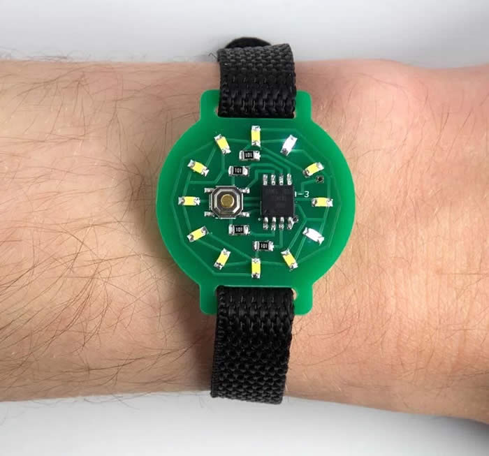
Here is my design for a minimalist ATtiny85-based watch using 12 LEDs, arranged like a clock face, to show the time analogue-style:
[contentblock id=1 img=adsense.png]
To show the time you press the button on the watch face, and the time is then displayed for four seconds. It lights one LED to show the hour, and flashes another LED to show the minutes to the nearest five minutes, like the hour and minute hands on a clock. If only one LED lights up you know that both hands are pointing to the same hour mark. The Tiny Time watch uses the ATtiny85’s built-in oscillator, fine-tuned to get it as accurate as possible, and my watch keeps time to within a couple of minutes over 24 hours. You can adjust the time by holding down the button for more than four seconds. It’s powered by a CR2032 button cell, and I’ve used several techniques to reduce the current consumption, so the battery should last for over a month. The total component cost, excluding the PCB, is about £5/$5, and it’s straightforward to build.
Read More: Mondaine Stop2Go Swiss Railways Watch
Introduction
I was inspired to design this watch after reading about Sam DeRose’s Nerd Watch which takes minimalism one step further. It seems fortuitous that you can drive 12 LEDs from four I/O lines using charlieplexing, exactly the number you need to display a clock face, taking advantage of the fact that you can drive two LEDs from every different pair of the I/O lines. One more I/O line is needed to detect the button press, neatly using the five I/O lines available on the ATtiny85.
[contentblock id=2 img=adsense.png]
Construction
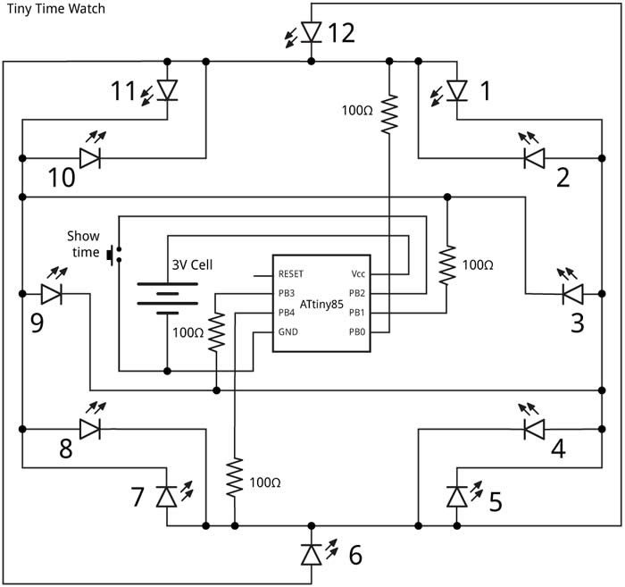
Here’s the circuit of the Tiny Time watch, laid out like the circuit board:
I built the watch on a small printed circuit board, using SMD components, with all the components apart from the battery holder soldered to one side of the board. I used an SOIC ATtiny85 and 0805 resistors and LEDs, so they are relatively easy to solder by hand. I arranged the LEDs to avoid tracks crossing in the layout which explains the rather haphazard order, but this is easily accomodated in the software. The following table shows which LED lights up when you take one I/O line high and the other I/O line low:
Read More: Monta Oceanking Dive Watch Review
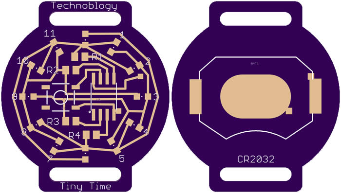
The button is a miniature SMD pushbutton available from Sparkfun , available from Proto-PIC in the UK , and the battery holder is an SMD 20mm coin cell holder also available from Sparkfun , or from Proto-PIC in the UK . The LEDs are 0805 size, and I chose white LEDs as they tend to be the brightest. I got mine from Bright Components in the UK, who sell them for under £1 for ten . The LEDs should be soldered with the same orientation, with the negative sides facing the centre of the board. I designed the board in Eagle and as an experiment sent it to both Seeed Fusion and OSH Park for fabrication. Here’s the preview from the OSH Park service:
There’s a link to the Eagle files at the end of the article if you want to make yourself a board. Alternatively, because the track layout avoids vias you could use a single-sided board, milled using a milling machine such as the Othermill; you could then glue the battery holder to the other side, and connect it through two holes to the main circuit. I used a Youyue 858D+ hot air gun at 250°C to solder the SMD components onto the front of the board, and then finally soldered the battery holder onto the back of the board using a conventional soldering iron.
[contentblock id=3 img=gcb.png]
If you don’t have a hot air gun you should be able to solder the SMD components with a bit of care using a fine-tipped soldering iron. I found a suitable 12mm wide thread-through watch strap from a German supplier.
The program
This section explains the various sections of the Tiny Time Watch program.
The display
The 12 LEDs are driven by the four I/O lines PB0, PB1, PB3, and PB4. PB2 is used for the push button, because it is assigned to the interrupt INT0, which makes detecting the button a bit easier. The array Pin[5][5] specifies how the LEDs are connected to the five I/O lines:


